Delve into the world of 3D modeling with our comprehensive Cinema 4D tutorial, covering topics such as Sweep Generator, Shapes and Lines, 2D shape creation, animation, and creating a modeling template.
This exercise is excerpted from Noble Desktop’s Cinema 4D Lite training materials and is compatible with Cinema 4D updates through 2023. To learn current skills in Cinema 4D with hands-on training, check out our Cinema 4D in After Effects Bootcamp, Motion Graphics Certificate, and video editing classes in-person and live online.
Topics Covered in This Cinema 4D Tutorial:
Sweep Generator, Shapes & Lines
Exercise Preview

Exercise Overview
In this exercise you will create an animate a sweep to write on some text.

Previewing the Final Video
Let’s see a preview of what you’ll be making. If you’re in After Effects, keep it open but switch to your Desktop.
On the Desktop, navigate to Class Files > C4D in AE Class > Spline Modeling—Sweep > Preview Movie and double–click Love Script.mp4.
-
Notice the following:
- The text writes on to the screen in a 3D version of the very popular write–on effect AE is know for.
Replay the video if you need to, and close it when done.
Getting Started
Open Cinema 4D Lite.
If you are just opening the application close the Quick Stat Dialog.
In C4D Lite, if you have a project open, choose File > Save.
Choose File > Close All Projects.
-
Choose File > Open Project.
- Navigate to C4D in AE Class > Spline Modeling—Loft
- Double–click on Love Script—Started.c4d to open it.
Choose File > Save Project As
Navigate to C4D in AE Class > Spline Modeling—Sweep
Name the file Your Name—Love Script.c4d
Press Save. We’re now ready to begin.
What is a Sweep?
In 3D modeling, the term “Sweep” refers to a 3D modeling technique that creates a 3D object by sweeping or stretching a 2D shape along a path. The Sweep generator allows you to create a wide range of shapes, from simple tubes and cylinders to more complex shapes like bottles, vases, and pipe systems.
To use the Sweep generator, you start by creating a 2D shape, or profile, and a path, which is a curve that defines the direction and trajectory of the sweep. You then use the Sweep generator to create the 3D object by sweeping the 2D shape along the path. The generator’s attributes provide many options for controlling the shape and appearance of the resulting 3D object such as the direction and orientation of the profile, and the number of segments.
Creating a Modeling Template
To save time in this lesson we have gone ahead and set up a reference for you to model from. It’s just a simple plane with an image texture but the template it provides makes it easier to create your 3D model. When modeling it is usually helpful to have some type of drawing as a reference. A helpful technique is to use your reference as the texture on a plane and then use that as your reference.
If you need to recreate your own you can follow these general steps:
-
In the Create Menu press and hold the Cube button to reveal the other primitive shapes.
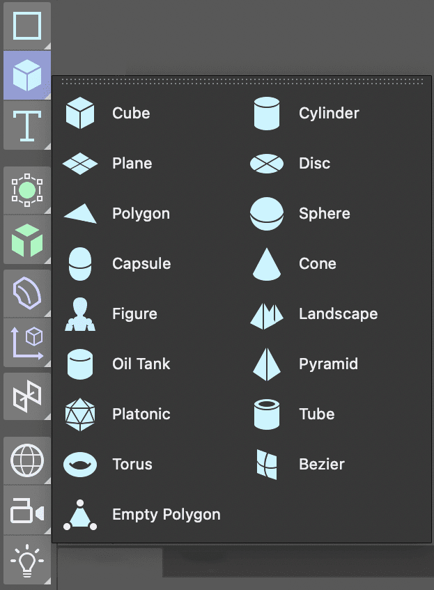
Select the Plane object from the list.
In the Perspective viewport click on the Toggle Active View
 button to reveal all four viewports.
In the Object Manager double–click on the Plane and rename it Model Reference or another name that wil make it easier for you to locate this object later.
Rotate the plane until it is facing towards you in the Front view.
-
In the Attribute Manager click on the Object tab and change the plane’s dimensions to match those of the image you are going to use as a reference.
NOTE: Since the default behavior of a material applied to an object is to stretch to fit it creating a plane so it’s the same siaze as your reference image will avoid distortions later.
-
Click in the Front view and press H or choose View > Frame Geometry.
- Repeat this for the other viewports.
In the Front viewport choose Display > Gouraud Shading. This will allow us to see the texture in the Front viewport once we apply it.
Click on the Material Manager
 button to open it.
Click on the New Default Material
 button.
-
Double–click on the new material’s name and rename it Model Reference.
- Press Return (Mac) or Enter (Windows) or click on any empty space to finalize the name change.
Double–click on the material’s icon
 to open the Material Editor.
In the Material Editor turn off the switch next to Reflectance. Having a refelctive model template can be very distracting.
Click on the Color map to make sure it’s active.
Click the arrow next to texture and choose Load Image.
-
Navigate to the image to use as your reference and double–click on it.
NOTE: If you image isn’t in the same root folder as your C4D file the application gives you the opportunity to make a copy of it there. This way you are less likely to misplace or move the files which would result in problems rendering later.
Close the Material Editor.
-
Drag the material from the Material Manager onto the Model Reference plane in the Object Manager.
NOTE: You can also drag a material directly onto your model in one of the viewports.
Close the Material Manager.
In the Object Manager click on the Model Reference object to select it.
Use the Move tool to push your reference image behind the origin. This way you wil be able to see the objects you create without them intersecting the plane.
-
For better organization we are going to place the reference image on its own layer.
- In the Object Manager CTRL–click (Mac) or Right–click (Windows) on the Model Reference object.
- Choose Add to New Layer. Notice that the little shape to the right of your object’s name lights up.
-
Locate the Layer Manager, it’s the panel named Layers.
- Double–click the new layer and rename it Reference.
- Click on the lock located beneath the L label.
NOTE: Each of the letter labels controls a diffrent property of the layer, the S solos the layer content, the V controls its visibility, etc. To see what each label represents choose open the View menu in the Layer Manager.
Click back on the Attribute Manager tab to reveal it. When a layer is selected this panel allows you to set its options.
Press Cmd–S (Mac) or CTRL–S (Windows) or choose File > Save Project.
Drawing a Path for the Sweep with the Spline Pen
The path for the sweep object can be either an open or closed spline and can be created with any spline tool. To create complex and flowing shapes you should use either the Spline Pen or Sketch tools.
Click on the Spline Pen
 tool to the left of the viewport.
In the Front view, adjust the viewport until you can comfortably see the reference image.
Continue to create a series of straight lines until you have the rough contour of the reference created.
Press the Esc key on your keyboard to finalize the spline.
Press the Spacebar on the keyboard to switch to your last used Selection
 tool.
tool.Select any vertex you want to convert from Hard Tangents (corners) to Soft Tangents (curves).
CTRL–click (Mac) or Right–click (Windows) on one of the selected vertices and choose Soft Interpolation.
Press E to activate the Move tool.
-
Drag this vertex’s tangent lines until the curves looks more like your reference image.
NOTE: You can also use the Move tool to move vertices around.
-
Continue to adjust vertices and tangents until you are happy with the results.
NOTE: To break Tangents so they are no longer linked together hold the Shift key while dragging. To delete a vertex, select it and press Delete (Mac) or Backspace (Windows) on your keyboard.

- Press Cmd–S (Mac) or CTRL–S (Windows) or choose File > Save Project.
The Sketch Tool
C4D has a tool designed to mimic the behavior of drawing by hand, it’s called the Sketch tool. Additionally, the Spline Smooth tool can soften or smooth off paths. Both tools are grouped with the Spline Pen.
- To activate the Sketch tool long–press on the spline pen.
- To use the tool click and drag naturally in any viewport.
- If the spline is too rough, use the Spline Smooth tool to soften it off.
Sweeping with a Shape
The second part of a sweep object is the shape that will extend or sweep along the path. This must be a closed spline.
-
In the Create menu, long–press on the Rectangle spline tool until the menu expands.
- Click on the Circle spline to create it.
NOTE: If you want to convert the circle to an oval click on the Elipse switch in the Attribute Manager.
-
In the Attribute Manager adjust the radius of the circle to your desired size.
NOTE: If the path has overlapping parts you will want to be careful to avoid too much intersection.
-
In the Create panel long–press on the Subdivision Surface generator until the menu expands.
- Choose Sweep from the menu.
Drag the path you created into the Sweep generator.
Drag the shape you created into the Sweep generator.
Rename the Sweep generator. Make sure the name is something descriptive that you can recognize later.
Adjust the path vertices to smooth off any rough parts of the sweep.
Press Cmd–S (Mac) or CTRL–S (Windows) or choose File > Save Project.

Modifying Sweep Properties
The Sweep object can be edited in the Attribute Manager
If it isn’t already selected, click on the Sweep object in the Object Manager.
-
If you have problems with sharp corners on your sweep object:
- In the Attribute Manager click on the Object tab.
- Click off the switch for Constant Cross Section.
Common Sweep Properties
End Scale: Determines the size of the contour at the end of the path. The contour is 100% at the start of the path and the size is interpolated in between.
End Rotation: Defines the rotation about the Z axis that the contour has passed through by the time it reaches the end of the path.
Start Growth: Works like End Growth, except that the Sweep object can be adjusted from the opposite end of the spline, i.e., from the spline’s start along its length.
End Growth: This option can be used to let a spline grow. A value of 100% will result in the spline contour being extended along the entire path. If applied to a closed spline, caps (without rounding) can be defined for intermediate stages.
Animating Sweep Properties
Any attribute in C4D that has a diamond next to it can be animated, this includes the properties of generators like Sweep. To animate the sweep so that the model is written–on from the beginning of the path. In this lesson you will gradually write–on the spline by animated one of the growth attributes.
Move the playhead to the beginning of the time ruler.
Select the object you want to animate.
In the Attribute Manager click on the Object tab.
Change End Growth to 0 (zero).
Click on the diamond
 to the left of the attribute to enable keyframes.
Move the playhead to where you want the next keyframe.
Change the End Growth attribute back to 100
-
Again click on the keyframe diamond
 to set a new keyframe.
NOTE: The keyframe diamond is red outlined this time. The appearance of the icon indicates the status of keyframes for the current property,
Press Cmd–S (Mac) or CTRL–S (Windows) or choose File > Save Project.