Explore the intricacies of AutoCAD, as this tutorial dives into specific features such as the Polyline tool for creating connected line segments and the Offset tool for creating copies of a polyline. These tools are essential for anyone looking to advance their career in architectural design or related fields.
Key Insights
- The AutoCAD's Polyline tool allows users to create connected line segments that are treated as one object, differentiating it from the Line tool which creates separate segments.
- The Offset tool is utilized to make an offset copy of a polyline, a feature commonly used in architectural design.
- The tutorial provides a step-by-step guide on creating a new drawing based on the Architectural-Imperial.dwt template and saving it as Pool.dwg.
- Users can set the Polar Tracking angle to 35˚ to facilitate the creation of the drawing.
- The tutorial further delves into the use of the Polyline and Offset tools to draw a patio around a pool and create a border around the pool for tiling.
- The exercise concludes by instructing on how to use the Polyline tool to draw a ladder, showcasing the tool's flexibility in assigning varying line weights to different segments.
In this exercise, you will use the Polyline tool to make connected line segments that will be treated as one object, as opposed to the Line tool which makes separate segments. You will also learn how to make an offset copy of a polyline with the Offset tool.
This exercise is excerpted from Noble Desktop’s past AutoCAD training materials and is compatible with Photoshop updates through 2020. To learn current skills in AutoCAD, check out AutoCAD Bootcamp and AutoCAD classes in NYC and live online.
Topics Covered in This AutoCAD Tutorial:
Polylines, Offset
Exercise Preview
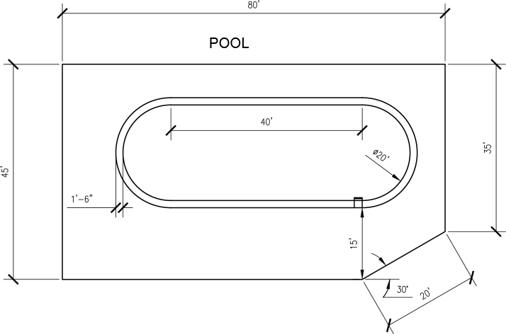
Exercise Overview
In this exercise, you will use the Polyline tool to make connected line segments that will be treated as one object, as opposed to the Line tool which makes separate segments. You will also learn how to make an offset copy of a polyline with the Offset tool.
Using the Polyline & Offset Tools
Start a new drawing based on the Archetectural-Imperial.dwt template. Save the file as Pool.dwg.
Set the Polar Tracking angle to 35˚.
-
Press the Polyline (PLINE) tool button
 on the Draw Panel (as shown below) or Toolbar, or type PL Enter.
-
Draw a polyline as shown in the diagram below to make the patio around the pool. By default, the Polyline tool behaves just like the Line tool. Press C Enter to use the Close option for the last line segment.
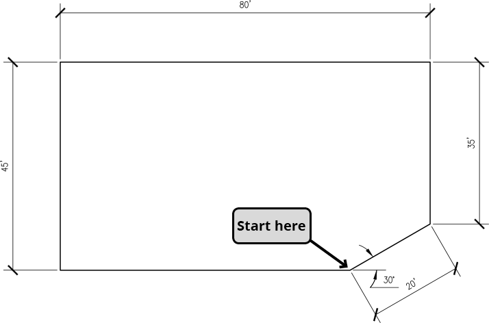
-
Repeat the Polyline Command
 . Use Extension to place the start point 16
'-6"above the lower-right corner of the patio as shown below. Once the start point has been established, options will appear in the Command Line. The first segment is an arc. Press A Enter to choose the Arc option. The Polyline tool creates 2 point arcs, meaning you will make a straight line that will be the diameter of the arc. Pull straight up along the X axis and enter a distance of 20'. You have created an Arc segment with a 20 foot diameter.
-
The Polyline tool is still in Arc mode. You will see a different set of options in the Command Line. Press L Enter to return to the Line mode for the next segment. Pull left on the Y axis and enter a distance of 40
'. The final segment is an Arc. Press A Enter to choose the Arc mode. Look again in the Command Line. There is a close option, but the keystroke is CL instead of C because there are multiple options that start with C. Press CL Enter to close the polyline with an Arc segment.
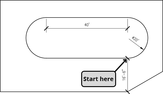
-
Now you will use the Offset command to make a border around the pool for tiling. One of the primary reasons for using the Polyline tool is so that you can create lines with multiple segments that can be offset as one entity with the Offset command. Press O Enter to start the Offset command. Enter 18
"for the Offset Distance. Unlike other Modify tools, the Offset command will first ask you to enter an Offset Distance, rather than select objects. This is so it will be easier to change the offset distance simply by double tapping the space bar to end and repeat the command. Select the edge of the pool for the object to offset, and then click anywhere outside the pool to specify a point on the side to offset. Press Enter or Escape to end the command. The Offset command will be covered in more detail in another chapter.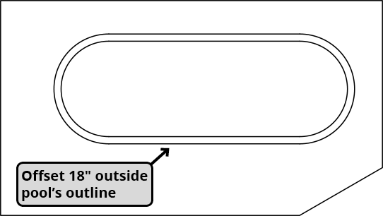
Offsetting Perimeters
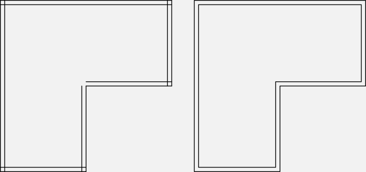
The image below depicts a perimeter made with the Line tool (on the left), and one made with the Polyline tool (on the right):
-
Now you will use the Polyline tool
 to draw the ladder. With the Polyline tool, you can assign varying line weights to different segments. You can even make an individual line segment have different widths at the start and end of the segment. When you assign line weight by layer or object, the line weight will always be uniform throughout the line or polyline.
Change the current layer to Misc. Start the Polyline command. Snap to the lower-right endpoint of the outer offset line of the pool as shown below. Once you’ve established the start point the Width option will appear in the Command Line. Type W Enter to choose the Width option. Enter 2 for the starting width. You will see in the command line that you must also enter an ending width. You can press Enter to repeat the starting width of 2
"for the ending width. When changing the width in the Polyline command, you must also enter a start width and an end width, even if those values are the same for a uniform line. Pull up on the X- axis and enter a distance of 2" as shown below. Press W Enter again. Press Enter to keep the Starting Width at 2", but enter an Ending Width of 4". Pull to the left on the Y axis and type a distance of 4"for the segment. For the next segment, enter a distance of 1"to the left on the Y axis without changing the width. If you don’t use the width option to change the line weight, the line width will be the same as the last ending width entered. Type W Enter to change the width again. Press Enter to keep the Starting Width of 4", and for the Ending Width, enter 2". For the last segment, pull down on the Y axis and enter a distance of 2", do not end the Polyline command. The width is still set at 2". Even if you end the command and restart it later, the width will still be set at 2", so you must reset the width. Press W Enter again and set the Starting Width and Ending Width to 0. Do not make another line segment, just press Escape or Enter to end the Polyline command.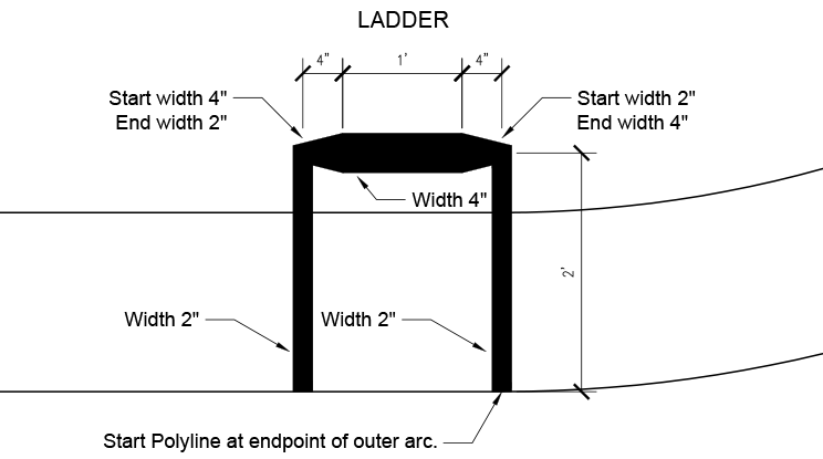
Close and save the file.


